Making a Solid-State Tesla Coil
Diagram and working theory of a solid-state Tesla coil generating Overunity - Free Energy
As some readers may feel that there is some "black magic" about the neon-driver circuit used by Don to drive the Tesla Coil section of his circuitry and that if a suitable unit could not be purchased then the circuit could not be reproduced or tested, it seems reasonable to show how it operates and how it can be constructed from scratch:
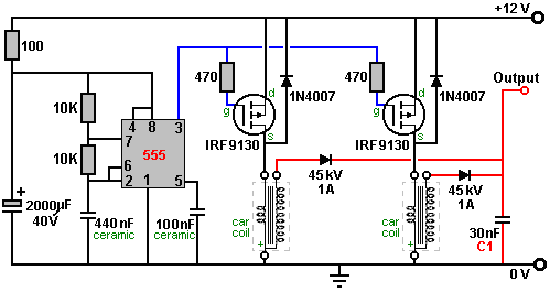
The circuit itself is made up of an oscillator to convert the 12-volt DC supply into a pulsating current which is then stepped up to a high voltage by a transformer. Here is a circuit which has been used for this:
The supply for the 555 timer chip is protected against spikes and dips by the resistor "R" and the capacitor "C". The 555 timer chip acts as an oscillator or "clock" whose speed is governed by the two 10K resistors feeding the 440 nF capacitor. The step-up transformer is an ordinary car coil and the drive power to it is boosted by the IRF9130 FET transistor which is driven by the 555 chip output coming from it's pin 3.
The output from the (Ford Model T) car coil is rectified by the diode, which needs to have a very high voltage rating as the voltage at this point is now very high. The rectified voltage pulses are stored in a very high-voltage capacitor before being used to drive a Tesla Coil. As a powerful output is wanted, two car coils are used and their outputs combined as shown here:
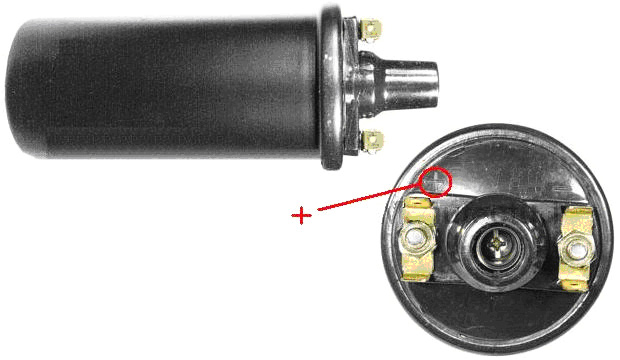
You will notice that the car coil has only three terminals and the terminal marked "+" is the one with the connection common to both of the coils inside the housing. The coil may look like this:
and the "+" is generally marked on the top beside the terminal with the two internal connections running to it. The circuit described so far is very close to that provided by a neon-tube driver circuit and it is certainly capable of driving a Tesla Coil.
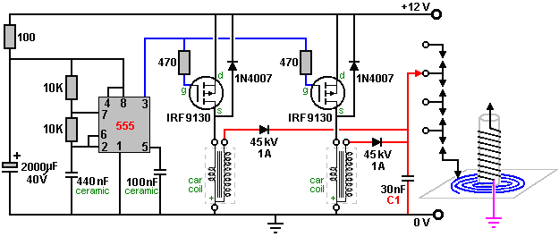
There are several different way of constructing a Tesla Coil. It is not unusual to have several spark gaps connected in a chain. This arrangement is called a "series spark gap" because the spark gaps are connected "in series" which is just a technical way of saying "connected in a row". In the chapter on aerial systems, you will see that Hermann Plauson uses that style of spark gap with the very high voltages which he gets from his powerful aerial systems. These multiple spark gaps are much quieter in operation than a single spark gap would be. One of the possible Tesla Coil designs uses a pancake coil as the "L1" coil as that gives even higher gain. The circuit is as shown here:
The connection to the pancake coil is by a moveable clamp and the two coils are tuned to resonance by careful and gradual adjustment of that connection, 10 mm at a time (after powering down and discharging the “C1” capacitor).
It has been found recently, that connecting two of these (non-ballast resistor) car coils back to back with the plus and minus connections switched over, that the performance is very much improved. It has been suggested that the small self-capacitance of each coil when connected across the other coil, causes a very much higher frequency of operation, giving much sharper voltage spikes which is a very desirable situation in a circuit of this type. This arrangement might be connected like this:
Note 1: That's the last diagram, which is considered to be the optimized scheme from the Tesla coil generating Free Energy. Lowering the voltage by the reverse Tesla coil will produce voltage at the output, but when there is a power dissipation device, the output power is greater than the input power (Overunity).
The series spark gap can be constructed in various ways, including using car spark plugs, gas-discharge tubes or neon lamps. The one shown here uses nuts and bolts projecting through two strips of a stiff, non-conducting material, as that is much easier to adjust than the gaps of several spark plugs:
The series spark gap can be constructed in various ways, including using car spark plugs, gas-discharge tubes or neon lamps. The one shown here uses nuts and bolts projecting through two strips of a stiff, non-conducting material, as that is much easier to adjust than the gaps of several spark plugs:
Tightening the bolts which compress the springs moves the bolt heads closer together and reduces all of the spark gaps. The electrical connections can be made to the end tags or to any of the intermediate wire connection straps if fewer spark gaps are required in the chain.
Let me remind you again that this is not a toy and very high voltages will be produced. Also, let me stress again that if you decide to construct anything, then you do so entire on your own responsibility. This document is only provided for information purposes and must not be seen as an encouragement to build any such device nor is any guarantee given that any of the devices described in this ebook will work as described should you decide to attempt to construct a replication prototype of your own. Generally, it takes skill and patience to achieve success with any free-energy device and Don Smith's devices are some of the most difficult, especially since he admits quite freely that he does not disclose all of the details.
The output capacitor marked "C1" in the circuit diagram above has to be able to handle very high voltages. There are various ways of dealing with this. Don dealt with it by getting very expensive capacitors manufactured by a specialist company. Some home-based constructors have had success using glass beer bottles filled with a salt solution. The outside of the bottles are wrapped in aluminium foil to form one of the contacts of the capacitor and bare wires are looped from deep inside each bottle on to the next one, looping from the inside of one bottle to the inside of the next one, and eventually forming the other contact of the capacitor. While that appears to work well, it is not a very convenient thing to carry around. An alternative is just to stand the bare bottles in a container which is lined with foil which forms the second contact of the capacitor.
One method which has been popular in the past is to use two complete rolls of aluminium foil, sometimes called "baking foil", laying them one flat, covering it with one or more layers of plastic cling film and laying the second roll of foil on top of the plastic. The three layers are then rolled up to form the capacitor. Obviously, several of these can be connected together in parallel in order to increase the capacitance of the set. The thicker the plastic, the lower the capacitance but the higher the voltage which can be handled.
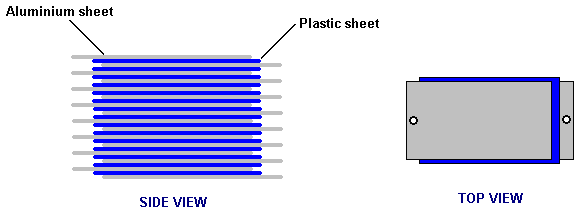
The November 1999 issue of Popular Electronics suggests using 33 sheets of the thin aluminium used as a flashing material by house builders. At that time it was supplied in rolls which were ten inches (250 mm) wide, so their design uses 14" (355 mm) lengths of the aluminium. The plastic chosen to separate the plates was polythene sheet 0.062 inch (1.6 mm) thick which is also available from a builders merchants outlet. The plastic is cut to 11 inch (280 mm) by 13 inch (330 mm) and assembly is as follows:
The sandwich stack of sheets is then clamped together between two rigid timber sheets. The tighter that they are clamped, the closer the plates are to each other and the higher the capacitance. The electrical connections are made by running a bolt through the projecting ends of the plates. With two thicknesses of plastic sheet and one of aluminium, there should be room for a washer between each pair of plates at each end and that would improve the clamping and the electrical connection. An alternative is to cut a corner off each plate and position them alternatively so that almost no plate area is ineffective.
As Don Smith has demonstrated in one of his video presentations, Nikola Tesla was perfectly correct when he stated that directing the discharge from a Tesla Coil on to a metal plate (or in Don's case, one of the two metal plates of a two-plate capacitor where a plastic sheet separates the plates just as shown above), produces a very powerful current flow onwards through a good earth connection. Obviously, if an electrical load is positioned between the plates and the earth connection, then the load can be powered to a high level of current, giving a very considerable power gain.
Note 2: The Free Energy (Overunity) generated from the solid state Tesla coil is Radiant Energy in nature. More research: Free Energy From Tesla Coil - Tesla Transformer Become Generator!
Note 2: The Free Energy (Overunity) generated from the solid state Tesla coil is Radiant Energy in nature. More research: Free Energy From Tesla Coil - Tesla Transformer Become Generator!
Radiant Energy:
🔹 Version from Nikola Tesla's Magnifying Transmitter🔹 The "tension" for "electricity fractionation" to occur is the Earth's Potential Potential. To be precise, it is the tension of the Ether, and the electricity is the dynamic polarization of the Ether.
🔹 During "Electricity segment", the magnetic field collapses several times in short periods of time. That leads the voltage V = Φ/t to reach infinity (V → ∞) when t → 0
- V - The electromotive force which results from the production or consumption of the total magnetic induction Φ (Phi). The unit is the “Volt”. Where t is the time of magnetic field collapse from maximum to complete collapse.
- Research scholars also call it Tesla's technology called Radiant Energy from Electronic Circuits, Impulse Technology.
Constructing High-Quality Coils
The Barker & Williamson coils used by Don in his constructions are expensive to purchase. Some years ago, in an article in a 1997 issue of the “QST” amateur radio publication, Robert H. Johns shows how similar coils can be constructed without any great difficulty. The Electrodyne Corporation research staff have stated that off-the-shelf solid tinned copper wire produces three times the magnetic field that un-tinned copper does, so perhaps that should be borne in mind when choosing the wire for constructing these coils.
These home-made coils have excellent “Q” Quality factors, some even better than the tinned copper wire coils of Barker & Williamson because the majority of electrical flow is at the surface of the wire and copper is a better conductor of electricity than the silver tinning material.
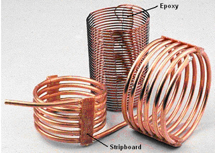
The inductance of a coil increases if the turns are close together. The capacitance of a coil decreases if the turns are spread out. A good compromise is to space the turns so that there is a gap between the turns of one wire thickness. A common construction method with Tesla Coil builders is to use nylon fishing line or plastic strimmer cord between the turns to create the gap. The method used by Mr Johns allows for even spacing without using any additional material. The key feature is to use a collapsible former and wind the coil on the former, space the turns out evenly and then clamp them in position with strips of epoxy resin, removing the former when the resin has set and cured.
Mr Johns has difficulty with his epoxy being difficult to keep in place, but when mixed with the West System micro fibres, epoxy can be made any consistency and it can be applied as a stiff paste without any loss of it’s properties. The epoxy is kept from sticking to the former by placing a strip of electrical tape on each side of the former.
I suggest that the plastic pipe used as the coil former is twice the length of the coil to be wound as that allows a good degree of flexing in the former when the coil is being removed. Before the two slots are cut in the plastic pipe, a wooden spreader piece is cut and it’s ends rounded so that it is a push-fit in the pipe. This spreader piece is used to hold the sides of the cut end exactly in position when the wire is being wrapped tightly around the pipe.
Two or more small holes are drilled in the pipe beside where the slots are to be cut. These holes are used to anchor the ends of the wire by passing them through the hole and bending them. Those ends have to be cut off before the finished coil is slid off the former, but they are very useful while the epoxy is being applied and hardening. The pipe slots are cut to a generous width, typically 10 mm or more.
The technique is then to wedge the wooden spreader piece in the slotted end of the pipe. Then anchor the end of the solid copper wire using the first of the drilled holes. The wire, which can be bare or insulated, is then wrapped tightly around the former for the required number of turns, and the other end of the wire secured in one of the other drilled holes. It is common practice to make the turns by rotating the former. When the winding is completed, the turns can be spaced out more evenly if necessary, and then a strip of epoxy paste applied all along one side of the coil. When that has hardened, (or immediately if the epoxy paste is stiff enough), the pipe is turned over and a second epoxy strip applied to the opposite side of the coil. A strip of paxolin board or strip-board can be made part of the epoxy strip. Alternatively, an L-shaped plastic mounting bracket or a plastic mounting bolt can be embedded in the epoxy ready for the coil installation later on.
When the epoxy has hardened, typically 24 hours later, the coil ends are snipped off, the spreader piece is tapped out with a dowel and the sides of the pipe pressed inwards to make it easy to slide the finished coil off the former. Larger diameter coils can be wound with small-diameter copper pipe.
The coil inductance can be calculated from:
Inductance in micro henrys L = d2n2 / (18d + 40l)
Where:
- d is the coil diameter in inches measured from wire centre to wire centre
- n is the number of turns in the coil
- l is coil length in inches (1 inch = 25.4 mm)
Using this equation for working out the number of turns for a given inductance in micro henrys:
Two types of power generation technology (generator) of Nikola Tesla
- 🔹 Radiant energy
- 🔹 AC generator - Free Energy
🔹 Tesla Technology and "Free Energy" in practical application

